Understanding the Cobra 19 Mini Mic Jack Pinout Diagram
If you're a radio enthusiast or a sound engineer, you've likely encountered the Cobra 19 Mini Mic. This compact, versatile microphone is a favorite among professionals for its reliability and performance. However, understanding its pinout diagram can be a bit tricky, especially if you're new to the world of radio equipment. In this article, we'll delve into the Cobra 19 Mini Mic Jack Pinout Diagram, providing you with a clear, concise guide to help you make the most of your microphone.
What is a Cobra 19 Mini Mic?
The Cobra 19 Mini Mic is a handheld, dynamic microphone designed for use with two-way radios. It's known for its durability, clarity, and versatility, making it suitable for a wide range of applications, from public safety to amateur radio. The microphone's compact size and lightweight design make it easy to carry and use, even in challenging environments.
The Importance of Understanding the Pinout Diagram
Before we dive into the pinout diagram, it's essential to understand why it's so important. The pinout diagram is a visual representation of the electrical connections within the microphone. It shows how the various wires inside the microphone are connected to the pins on the microphone's jack. Understanding this diagram is crucial for several reasons:
- Troubleshooting: If your microphone isn't working correctly, knowing the pinout diagram can help you identify and fix the problem.
- Repairing: If your microphone is damaged, understanding the pinout diagram can help you repair it.
- Connecting to Different Devices: The pinout diagram can help you connect your microphone to different devices, such as a radio or a sound system.
The Cobra 19 Mini Mic Jack Pinout Diagram
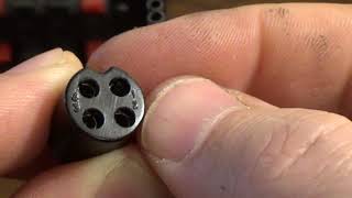
The Cobra 19 Mini Mic has a 5-pin jack. The pinout diagram for this microphone is as follows:
- Pin 1: This pin is connected to the microphone's ground.
- Pin 2: This pin is connected to the microphone's positive (+) power supply.
- Pin 3: This pin is connected to the microphone's negative (-) power supply.
- Pin 4: This pin is connected to the microphone's output signal.
- Pin 5: This pin is also connected to the microphone's ground.
It's important to note that the pinout diagram can vary slightly depending on the manufacturer and the specific model of the microphone. Therefore, it's always a good idea to double-check the pinout diagram for your specific microphone.
How to Use the Pinout Diagram
Now that you understand the pinout diagram, let's discuss how to use it. The pinout diagram can be used in several ways:
TroubleshootingIf your microphone isn't working correctly, the first thing you should do is check the connections. Make sure that all the wires are properly connected to the correct pins on the microphone's jack. If you're unsure about the connections, you can use the pinout diagram as a guide.
RepairingIf your microphone is damaged, you can use the pinout diagram to help you repair it. For example, if a wire is broken, you can use the pinout diagram to identify which wire it is and how it should be connected.
Connecting to Different DevicesThe pinout diagram can also be used to help you connect your microphone to different devices. For example, if you want to connect your microphone to a sound system, you can use the pinout diagram to ensure that the microphone's output signal is connected to the sound system's input.